Why Two Different Control Modes?
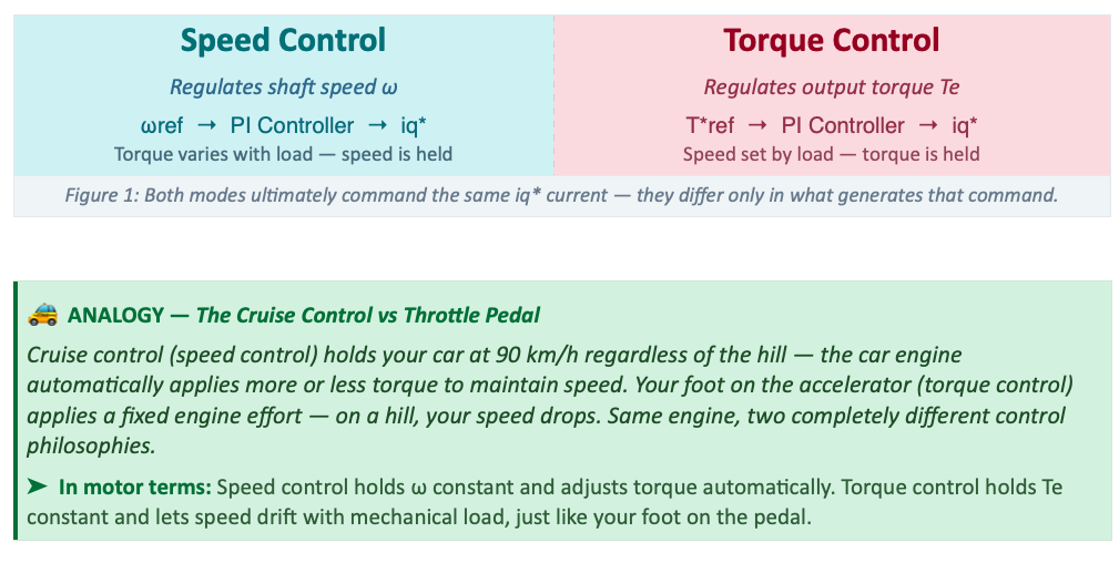
Every motor controller must answer a fundamental question: what am I trying to hold constant? The answer splits the entire world of motor control into two paradigms: regulate the shaft speed and let torque be a free variable, or regulate the output torque and let speed be determined by the mechanical load.
This distinction matters enormously. Speed Control and Torque Control have radically different dynamic behaviour, different feedback structures, different bandwidth characteristics, and different ideal application domains. Choosing the wrong one is a common source of poor drive performance.
Control Loop Architectures
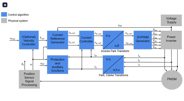
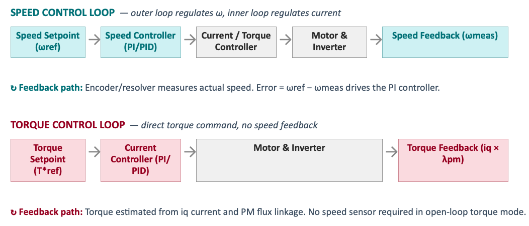
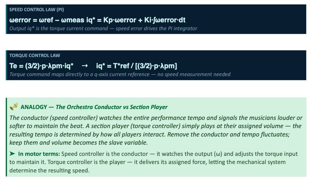
The fundamental structural difference between the two modes lies in how the command signal reaches the current (torque-producing) controller. Speed control adds an outer feedback loop around the existing current loop — torque control uses only the inner current loop directly.
Graph 1 — Step Response Comparison
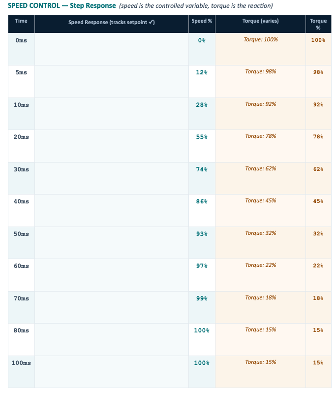
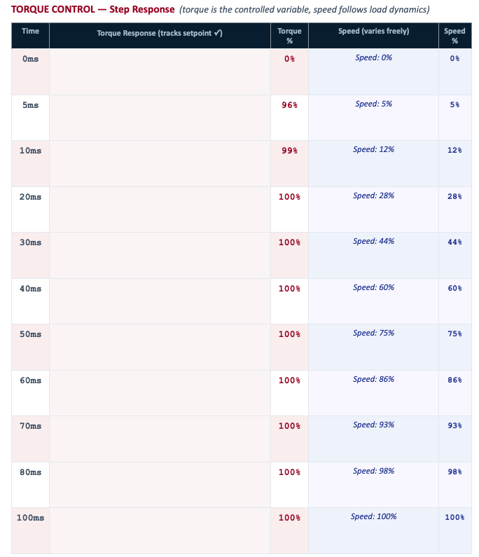
When a step command is applied at t = 0, Speed Control and Torque Control exhibit fundamentally different transient behaviour. Each row in the table below represents a simulation time step, with the bar showing how far the controlled variable has reached its setpoint.

Graph 2 — Load Disturbance Response
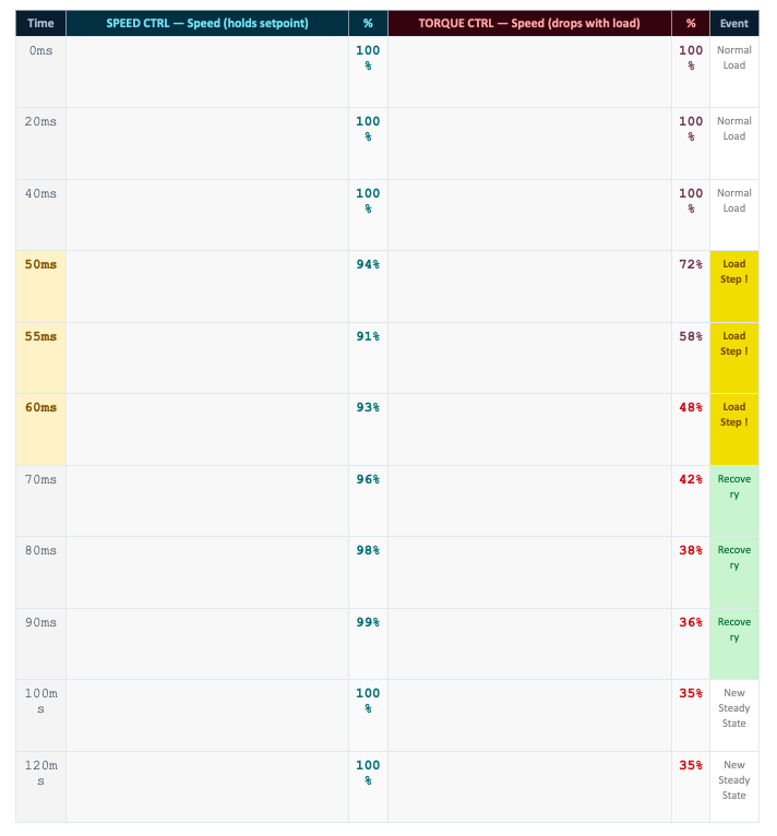
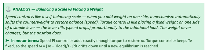
A sudden increase in load torque (step at t = 50ms) is one of the most revealing tests for a drive system. The table below shows how each control mode responds — teal bars for Speed Control (speed is held), faded bars for Torque Control (speed drops).
Graph 3 — Performance Profile
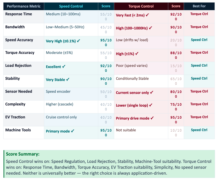
Across 10 performance dimensions, Speed Control and Torque Control each have distinct strengths. The score column (out of 100) quantifies relative performance — a checkmark (✓) marks the winner for each metric.
Graph 4 — Application Suitability Map
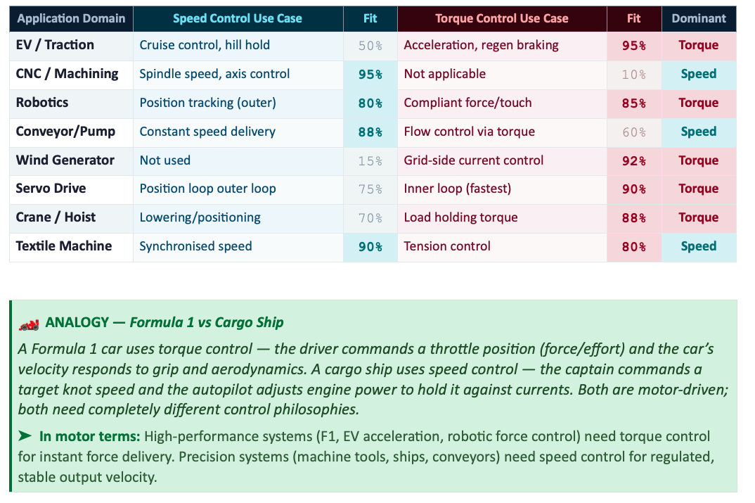
Different industries demand different control modes. The application map below rates the fit of each control mode for eight major drive domains. A score ≥ 80% is highlighted — use it to quickly identify which mode is dominant in your target application.
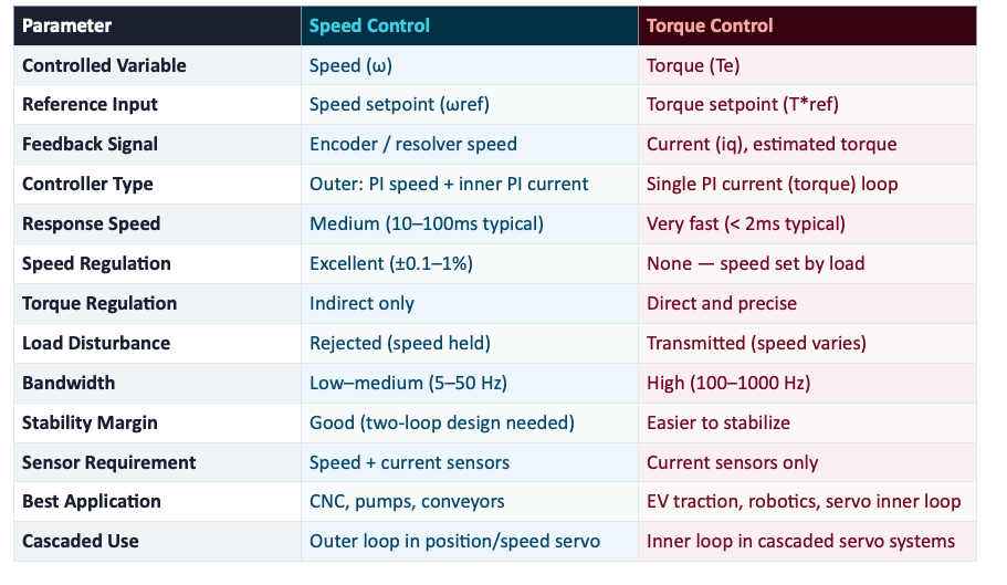
Full Parameter Comparison
The table below provides a complete side-by-side reference across all key parameters. Use this as a quick decision guide when specifying or designing a drive system.
Cascaded Control — Using Both Together
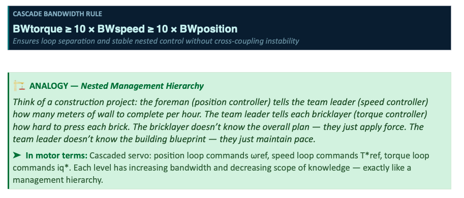
The most powerful servo systems cascade all three loops: position, speed, and torque. Each outer loop commands the setpoint of the inner loop. Torque control forms the fastest, innermost layer — speed control wraps around it — and position control wraps around speed.

Bandwidth rule of thumb: Each outer loop must be at least 5–10× slower than the inner loop to prevent interaction. Typical values: torque loop ~1 kHz, speed loop ~100 Hz, position loop ~10 Hz.
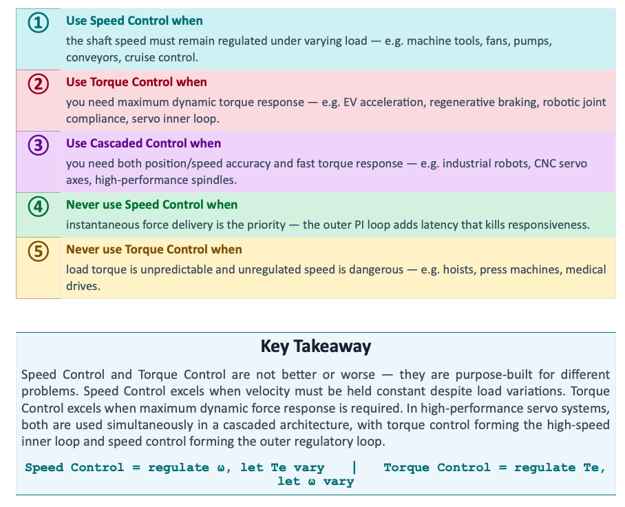
Decision Guide: Which Mode to Choose?