1. What is a PMSM Motor?
A Permanent Magnet Synchronous Motor (PMSM) is the type of electric motor used in most modern electric vehicles and industrial servo systems. It uses strong permanent magnets built into the rotor (the spinning part) to create a magnetic field. The stator (the stationary outer part) has coils of wire that carry electric current. The interaction between the stator current and the rotor magnets produces torque — the turning force that spins the shaft.
The motor spins at a speed that is directly proportional to the frequency of the electrical supply. The control system’s job is to decide how much current to send, in what direction, and at what frequency — all several thousand times per second.
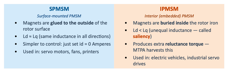
1.1 Two Types: Surface vs Interior PMSM
There are two common designs, and the difference matters for how we control them:

2. Understanding id and iq — The Two Control Levers
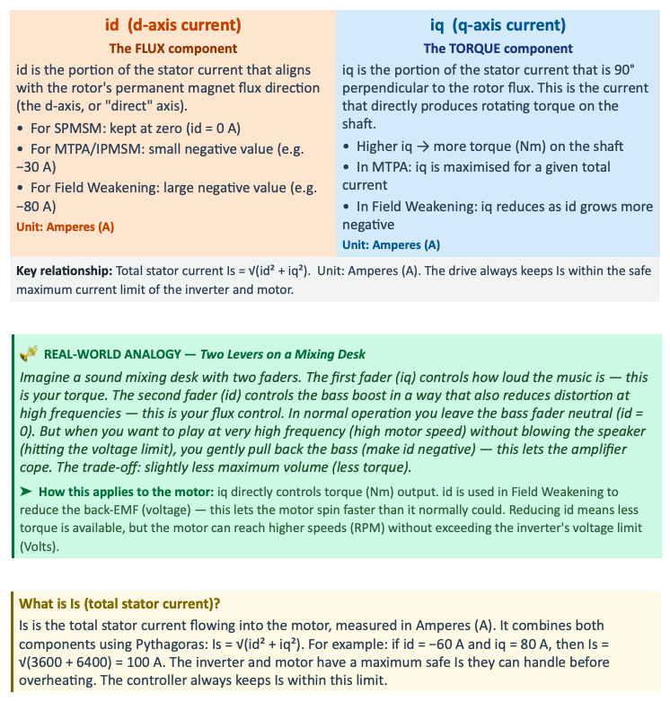
To control a PMSM motor, engineers use a clever mathematical trick: instead of controlling three separate AC currents (ia, ib, ic in Amperes), they transform them into just two DC-like values — id and iq. Think of id and iq as two independent control levers on a mixing desk.
3. MTPA — Maximum Torque Per Ampere

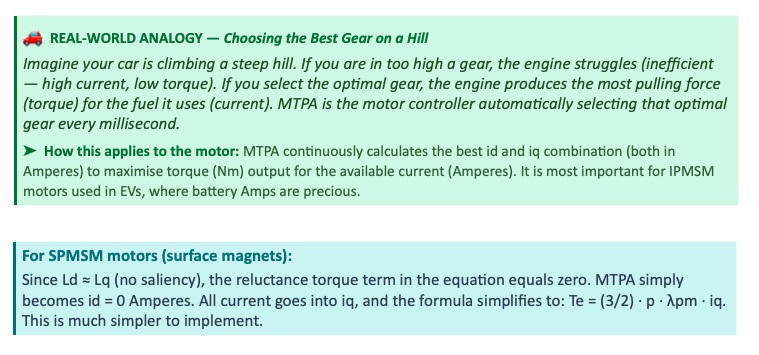
MTPA is used when the motor is running below its base speed (for example, below 3000 RPM). In this speed range, the motor has enough voltage available from the inverter — so the only thing limiting us is current. MTPA makes the most of every Ampere we put in.
For a simple SPMSM (surface magnets, no saliency), MTPA is trivial: just set id = 0 A and put all current into iq. For an IPMSM (interior magnets, saliency), MTPA tilts the current vector slightly — using a small negative id — to also generate reluctance torque alongside the normal PM torque. This gives more total torque (Nm) for the same total current (Amperes).

The two terms in the torque equation represent: (1) the PM flux torque from the permanent magnets (always present), and (2) the reluctance torque, which only exists in IPMSM motors where Ld ≠ Lq. MTPA finds the id/iq split that maximises the sum of both terms.
4. Field Weakening — Going Beyond Base Speed
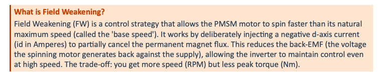
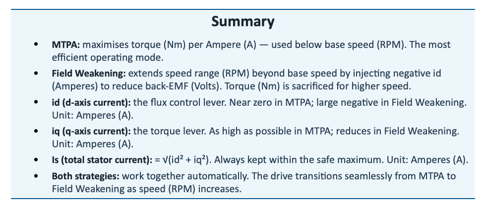
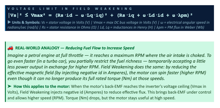
As the motor spins faster and faster, the back-EMF voltage it generates increases. Eventually this back-EMF approaches the maximum DC bus voltage the inverter can supply (measured in Volts). At this point — called base speed — the inverter can no longer push more current in using normal control. Without Field Weakening, the motor would be stuck at this speed limit.
Field Weakening solves this by pushing negative current into the d-axis (id < 0 A). This current flows in opposition to the permanent magnet flux, partially cancelling it — reducing the effective flux and therefore reducing the back-EMF. The inverter can now maintain control and push the motor to even higher speeds (RPM).
5. Torque–Speed Envelope — What It Looks Like
The table below shows how the motor behaves at different speeds. All values assume a typical EV traction motor with a base speed of 3000 RPM and a rated torque of 150 Nm. The * values are examples — your actual motor will have different numbers.
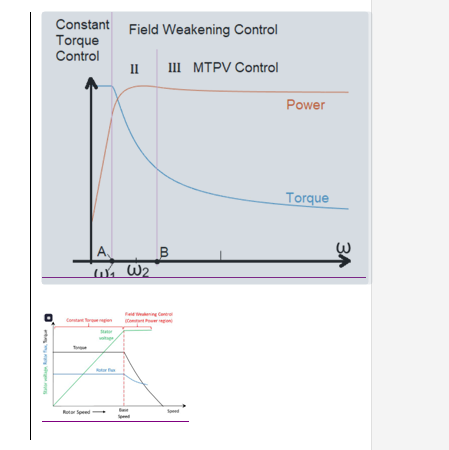
Figure 1: Complete PMSM Operating Envelope showing Constant Torque (MTPA), Field Weakening, and MTPV regions.
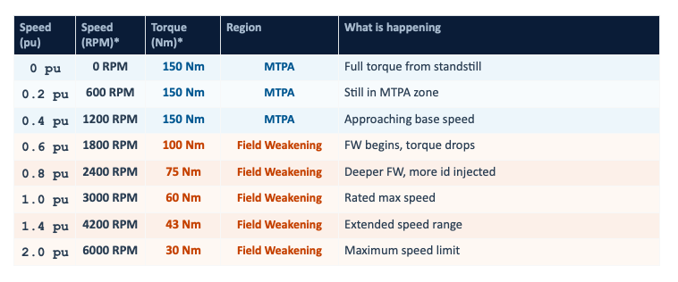
* Example values for a typical 50 kW EV traction motor. pu = per unit (a fraction of the base/rated value). 1.0 pu speed = base speed = 3000 RPM in this example.
6. How id and iq Change With Speed
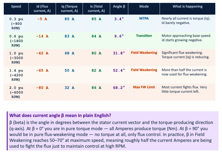
The table below shows how the d-axis current (id) and q-axis current (iq) — both in Amperes — change as the motor accelerates from low speed through Field Weakening. The current angle β (in degrees) shows how far the current vector is tilted away from the pure torque direction.
The angle β = 0° means all current is in the torque direction (iq). As β increases toward 90°, more and more of the total current Is is being used to fight the flux (id) rather than produce torque (iq). This is the cost of Field Weakening.
7. MTPA vs Field Weakening — Full Comparison
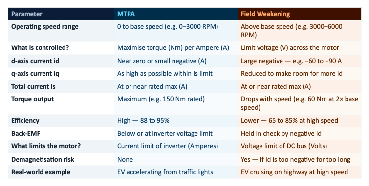
The table below summarises the key differences between the two strategies with proper units throughout:
8. How They Work Together
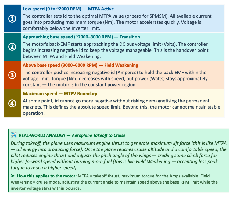
In a real EV or servo drive, MTPA and Field Weakening are not separate modes you pick from a menu. The controller transitions automatically and seamlessly between them based on the motor speed (RPM) and the available DC bus voltage (Volts). The driver just presses the accelerator — the drive controller handles the rest.
9. Key Things to Get Right in a Real Drive
If you are implementing MTPA and Field Weakening in a motor controller, these are the five most important practical considerations:
- Motor parameter accuracy: You need accurate values for Ld (Henry), Lq (Henry), λpm (Weber), and Rs (Ohms). Even 5–10% error in these values causes the MTPA angle to be wrong, meaning you extract less torque (Nm) per Ampere than the motor is capable of.
- Look-up tables (LUTs): Rather than solving the MTPA equation in real time (computationally expensive), controllers pre-calculate the optimal id/iq values (Amperes) for every combination of torque demand and speed (RPM), and store them in a lookup table that is accessed in microseconds.
- Voltage margin: Always keep the stator voltage Vs (Volts) about 5–10% below the maximum Vmax. This headroom handles sudden transients and ensures the PWM inverter does not saturate.
- Temperature compensation: The PM flux linkage λpm (Weber) weakens as the magnets heat up. The winding resistance Rs (Ohms) also rises with temperature. Without compensation, the MTPA point and FW boundary shift, reducing performance at operating temperature.
- Demagnetisation protection: If id (Amperes) becomes too negative for too long, the permanent magnets can lose their magnetisation permanently. The controller must limit the maximum negative id based on the magnet grade and operating temperature.