We know CAN is the backbone of in-vehicle communication, but have you ever wondered how AUTOSAR structures this data flow from application to hardware — and back?
If you are familiar with the basics of AUTOSAR architecture and want to understand its CAN communication stack and data flow, this blog will serve as a comprehensive starting point.
The AUTOSAR COM Stack refers to a specific part of the AUTOSAR (AUTOmotive Open System ARchitecture) layered architecture responsible for communication between software components and between ECUs (Electronic Control Units) over a vehicle network, such as CAN, Ethernet, FlexRay, or LIN.
In this blog, we will only focus on the CAN communication stack.
The AUTOSAR CAN Stack is a set of software modules that work together to send and receive data over the CAN bus.
The modules involved in transmitting/receiving CAN messages are shown in the fig. below:
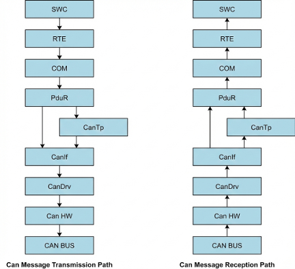
(Note: CanTp only comes in picture when data length is > 8 bytes or when dealing with the UDS messages)
- SWC (Software Component): Application code to send or receive signals (like speed, temperature, etc.)
- RTE: Passes signals between the application (SWC) and lower layer module (COM).
- COM: Packs/unpacks signals into a PDU (Protocol Data Unit).
- PduR: Routes the PDU between COM and the CanTp (if data more than 8 bytes), else routes it between COM and CanIf.
- CanTp: Segments and reassembles CAN PDUs longer than 8 bytes that do not fit in a single frame.
- CanIf: Manages different CAN controllers and transceivers. Also, handles PDU to message buffer mapping.
- CanDrv: Talks directly to the CAN hardware (controller). Sends or receives CAN frames.
Apart from the above modules, a few more modules have a specific role in managing the CAN communication:
(No data flow happens from these modules)
- CanSM: Manages the overall state transitions of the CAN communication.
- CanNM: Responsible for initiating the wake-up and shutdown of the CAN network. (If configured, might send NM frames. No application data flows from here)
- ComM: Manages different communication modes of different network channels (e.g., CAN, LIN, Ethernet) in an ECU.
- CanTrcv: Handles the mode transitions and wakeup of the CAN transceiver hardware chips on an ECU.
1. CanDrv Module
- The CanDrv module is a Microcontroller Abstraction Layer (MCAL) component in AUTOSAR.
- Provides services for initiating transmissions.
- Provides notification to the CanIf module regarding transmission and reception of data/message.
- Provides services to control the state of the CAN controllers.
Configuration Parameters:
Here we mainly configure,
- the CAN controllers in the ECU,
- Baud rate configuration (configuring the time segments and prescaler values),
- Message buffers/Hardware Objects configuration (configuring the type (FULL_CAN or BASIC_CAN) and the Hardware filters for Rx MB (Message Buffers)).
Terminology:
- Hardware Objects: A physical CAN hardware buffer or mailbox within the CAN controller’s RAM. These objects are used to transmit and receive CAN frames.
- FULL CAN: Only one PDU is allocated for one Hardware Object/MB.
- BASIC CAN: Multiple PDUs are allocated for one Hardware Object/MB.
- Acceptance Code (Hw Filter): The CAN ID bits that you want to get.
- Acceptance Mask (Hw Filter): The CAN ID bits that you want to filter.
2. CanIf Module
- CanIf acts as a middleware between the upper layer modules (i.e., CanSM, CanNM, CanTp, PduR) and the lower layer modules (CanDrv and CanTrcv).
- Manages different CAN controllers and CAN transceivers.
- Manages the mapping between the PDUs and the message buffers.
- Provides services for transmission request, transmission confirmation, reception indication, controller mode control, and PDU mode control.
Configuration Parameters:
Here we mainly,
- provide the references of the Can Controllers used, Hardware Objects configured, Can Transceivers used,
- do Mapping of PDUs and the hardware objects (HTH and HRH).
- configure the CanID, CanID type (Standard/Extended CAN), DLC and the upper layer of the PDU.
3. CanTp Module
- CanTp is the module between the PDU Router and the CAN Interface module.
- The main purpose of the CAN TP module is to segment and reassemble CAN PDUs longer than 8 bytes or longer than 64 bytes (in case of CAN FD) that do not fit in a single CAN frame.
Configuration Parameters:
Here, we mainly do the linking of the N-SDUs with the N-PDUs. Make sure you provide the appropriate references to the PDUs.
Terminology:
- SDU: An SDU (Service Data Unit) is the complete data/payload to be transmitted/sent. It can be longer than 8 bytes and later be segmented in CanTp module.
- PDU: A PDU (Protocol Data Unit) contains the SDU (the payload) and the PCI (Protocol Control Information). It corresponds to one CAN frame (max 8 bytes for classical CAN).
4. PduR Module
- PduR module is a central routing hub in the communication stack. It connects different upper-layer and lower-layer modules by routing Protocol Data Units (PDUs) between them.
- Offers single cast (1:1), multicast (1:n), and gateway transmission and reception.
Configuration Parameters:
Here, we mainly configure
- The BSW modules involved in routing the PDUs,
- Routing path of the PDUs (Source and Destination PDUs).
5. COM Module
- COM is the module between the RTE and the PDU Router.
- Handles the packing and unpacking of the signals in the PDU to be transmitted and received.
- Also provides different notification mechanisms, transmission modes, and timeout configurations per PDU.
Configuration Parameters:
Here, we mainly map the signals/signal groups to the PDUs.
This includes configuring:
- the direction (SEND/RECEIVE), PDUType (NORMAL/TP), and the transmission mode of the PDU.
- the bit position, bit size, signal type, and endianness of the signals.
6. RTE
- The RTE (Run-Time Environment) is a middleware layer that provides communication between Application Software Components (SWCs) and between SWCs and the Basic Software (BSW) modules.
- Responsible for mapping of signals/signal groups from COM with the application signals, and also handles mapping of RTE and BSW events with the OS tasks.
Configuration Parameters:
With respect to the CAN data transmission and reception, we mainly do,
- data mapping (Map signals/signal groups from COM with the application signals)
- event mapping (Map Runnables and Main functions to the OS task).
7. SWC
- A SWC or software component is a component that has application logic. In AUTOSAR, a functionality is encapsulated by an SWC.
- SWCs communicate with each other or with lower layers (BSW layers) by using ports with the help of RTE.
- Using tools like DaVinci Developer/Autosar Builder, we mainly define how the SWC communicates, executes, and interacts with the rest of the system.
Configuration Parameters:
Here we mainly configure the ports, port interfaces, Runnables, events, and data elements to be used by the SWC.
With respect to the CAN data transmission (Tx) and reception (Rx), we mainly need to
- configure a runnable which handles the CAN Tx and Rx either periodically or event-based,
- create application data elements which will be mapped with the signals of the COM module for Tx and Rx.
8. CanSM
- The CanSM (CAN State Manager) module in AUTOSAR is part of the Service Layer and is responsible for managing the state of CAN communication across different CAN channels.
- Works in coordination with CanIf, CanNM, and ComM to control and monitor the communication mode.
- Ensures that CAN communication starts, stops, or transitions between states properly, based on requests from upper layers like ComM.
Configuration Parameters:
Here we mainly configure the,
- CAN Networks (Providing reference of the CAN controllers in the particular CAN BUS),
- Bus off recovery mechanism, Bus off timing parameters and DEM event reporting if bus off.
9. ComM
- The ComM (Communication Manager) module in AUTOSAR is a Service Layer module that centrally manages the communication mode of each network in the system.
- Allows application (SWC) or BswM to request the communication modes and coordinates the same to the state managers (like CanSM, LinSM, or FrSM).
Configuration Parameters:
Here we mainly configure,
- Different types of network channels (CAN, LIN, ETH, FR, etc)
- and the channel users (A user may be the BswM, a runnable entity, a SW-C, or a group of SW-Cs).
Example
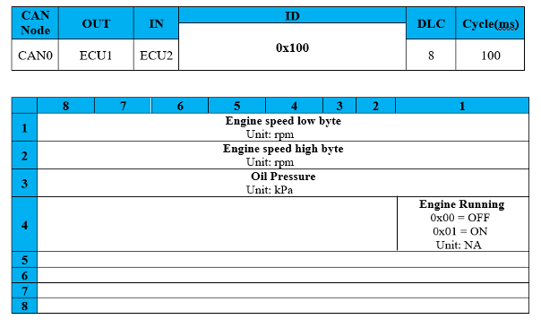
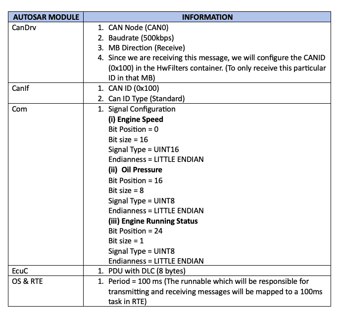
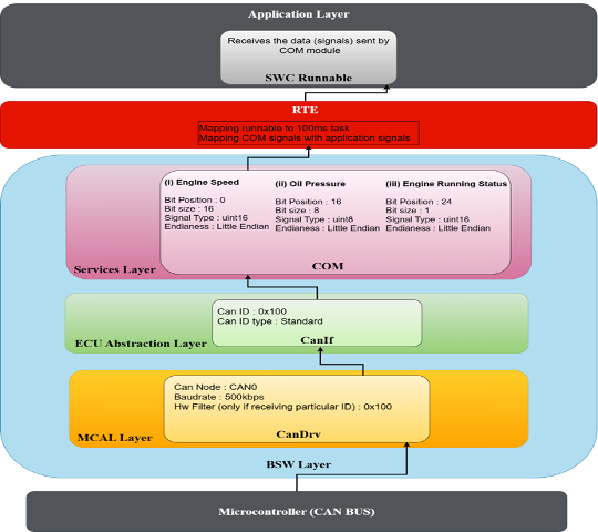
We will consider a CAN message and check where we will configure all the information from the CAN message in the AUTOSAR CAN Stack.
The message shown below is the Rx data, which we will be receiving from ECU1 at a 500kbps baud rate