
Introduction
The SR-IOV Demonstration Technology is a hardware-based virtualization solution that improves both performance and scalability. The SR-IOV standard enables efficient sharing of PCIe (Peripheral Component Interconnect) Express devices among virtual machines and is implemented in the hardware to achieve I/O performance which is comparable to native performance
The SR-IOV standard allows efficient sharing of PCIe devices among IO Guest Domains. An SR-IOV device can have hundreds of Virtual Functions (VFs) associated with a Physical Function (PF).
Devices that have SR-IOV capability can take advantage of the following benefits:
- Performance – Direct access to hardware from a virtual machine environment.
- Cost Reduction – Capital and operational expenditure savings include:
- Power savings
- Reduced adapter count
- Less cabling
- Fewer switch ports

Problem
- The Customer wanted an implementation of the Driver for SR-IOV supported 10 Gig Ethernet NIC Endpoint.
- Meet the near-native performance for all VMs and Host OS.
- Meet the industry benchmark of 64-byte length and 1.5K byte length payload packets.
- Develop a Drivers to support on x86 and ARM architectures
- Test the Driver for FPGA Model of the IP ((while the Silicon was getting ready) and then on the Silicon version
Challenges
Set-up Challenges
- Finding the right host machine which supports SR-IOV at HW level and FW level
- Finding the right HV that supports both on x86 and ARM architectures
- Set-up 1 Gig network environment for testing
Design Challenges
- Implementing the PF and VF Drivers to accomplish SR-IOV functionality
- Cope with changes that are introduced in the RTL model during the development cycle
- Architect the SR-IOV Driver (PF and VF) to share the configuration area and to exchange messages to work synchronously.
- Designing of the test cases to test all the features, including, stress tests, performance tests, long-run tests and negative tests
Solution
- Design PF and VF Drivers
- PF Driver takes care of all the configuration of NIC HW.he PF and these configurations are common to all the VFs and PF.
- The PF Driver also takes care of Interrupt set-up. These are Ethernet packet interrupts and mailbox interrupts
- The VF Driver takes care of the allocation of native Descriptors for each of the VMs
- Implement a Mailbox interface to share commands between PF and VF
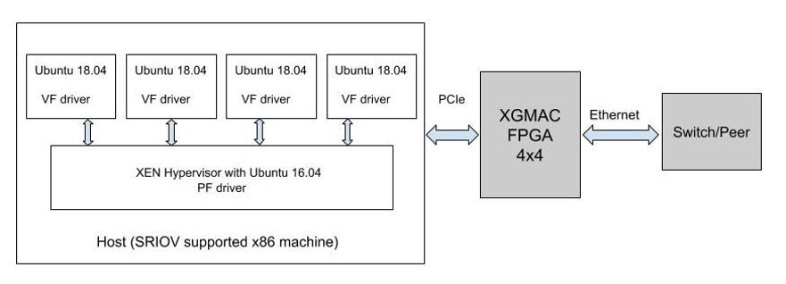
Implementation
Implemented PF and VF Drivers on HV (KVM and Xen) and Linux OS respectively
Description of PF operation
The Physical Function (PF) is a PCI Express (PCIe) function of a network adapter that supports the single root I/O virtualization (SR-IOV) interface. The PF includes the SR-IOV Extended Capability in the PCIe configuration space. The capability is used to configure and manage the SR-IOV functionality of the network adapter, such as enabling virtualization and exposing PCIe Virtual Functions (VFs).
The configuration and provisioning of the VFs, together with other hardware and software resources for the support of VFs, is performed through the PF driver. The PF driver provides the access to the networking I/O resources to the management operating system. The PF driver is also used as a way to manage the resources allocated on the adapter for the VFs.
Description of VF operation
A PCI Express (PCIe) Virtual Function (VF) is a lightweight PCIe function on a network adapter that supports single root I/O virtualization (SR-IOV). The VF is associated with the PCIe Physical Function (PF) on the network adapter and represents a virtualized instance of the network adapter. Each VF has its own PCI configuration space. Each VF also shares one or more physical resources on the network adapter, such as an external network port, with the PF and other VFs.
A VF is not a full-fledged PCIe device. However, it provides a basic mechanism for directly transferring data between a Hyper-V child partition and the underlying SR-IOV network adapter. Software resources associated for data transfer are directly available to the VF and are isolated from the use by the other VFs or the PF. However, the configuration of most of these resources is performed by the PF Miniport driver that runs in the management operating system of the Hyper-V parent partition.
A VF is exposed as a virtual network adapter (VF network adapter) in the guest operating system that runs in a Hyper-V child partition. After the VF is associated with a virtual port (VPort) on the NIC switch of the SR-IOV network adapter, the virtual PCI (VPCI) driver that runs in the VM exposes the VF network adapter. Once exposed, the PnP manager in the guest operating system loads the VF Miniport driver.
Testing
Feature Tests:
| # | Feature |
| 1 | All DMA channel allocation across PF and VF |
| 2 | Configuring Traffic class |
| 3 | VLAN stripping |
| 4 | VLAN filtering |
| 5 | Promiscuous mode(VF will be tested after ELI support) |
| 6 | Set VF MAC |
| 7 | Ethtool ops |
| 8 | Get PTP timestamp (PTP in VF needs multicast support in Module, VF will be tested after ELI support) |
| 9 | Checksum Offloading |
| 10 | Transmit Segmentation Offload (TSO) |
| 11 | multi-cast |
| 12 | Broadcast (FPFA support needed for VF Broadcast test,VF will be tested after ELI support) |
Negative Tests:
| # | Feature |
| 1 | Invalid max_vfs value |
| 2 | Running VMs more than mx_vfs and loading VF drivers on them |
| 3 | Setup repeated VLANs on the interface |
| 4 | Assigning already existing PF interface VLAN ID to VF interface or VF interface VLAN ID to PF interface |
| 5 | Killing a non-existing VLAN ID |
| 6 | Assigning VLAN ID outside the maximum DMA channel present for each configuration |
| 7 | Setting of parameters outside the range. The maximum range supported for rx-usecs is 2611(for PF) and 522 (for VF) |
| 8 | Setting of channel number outside the range of 4(for 4×4 configuration), 3(for 5×3 configuration) and 2(for 8×2 configuration). |
| 9 | Setting ring parameters outside the range. The maximum range supported for rx and tx ring is 4096 |
Stability Tests:
| # | Test |
| 1 | Continuous data transfers for duration of 10 hours |
| 2 | Data transfer test with the cable being removed and connected back. No drop in the throughput rate expected after the cable is reinserted |
| 3 | Interface up and down multiple times using ifconfig command and verify whether the setup is stable |
| 4 | Remove PF without removing VF |
| 5 | Overnight youtube test on PF and VFs |
| 6 | Overnight SCP test on PF and VFs |
| 7 | OVernight iPerf test on PF and VFs |
| TCP/UDP | Command | Bandwidth | |
| PF as Server and Laptop as Client | |||
| PF | Laptop | ||
| TCP | iperf3 -s | iperf3 -c 50.40.2.58 -t 20 -l64 | ~(X/5) Mbps |
| UDP | iperf3 -s | iperf3 -c 50.40.2.58 -u -b1G -t 20 -l64 | ~(X/5) Mbps |
| PF as Server and Laptop as Client | |||
| TCP | iperf3 -s | iperf3 -c 50.40.2.20 -t 20 -l64 | ~(X/5) Mbps |
| UDP | iperf3 -s | iperf3 -c 50.40.2.20 -u -b1G -t 20 -l64 | ~(X/5) Mbps |
| TCP/UDP | Command | Bandwidth | |
| PF as Server and Laptop as Client | |||
| PF | Laptop | ||
| TCP | iperf3 -s | iperf3 -c 50.40.2.58 -t 20 | ~X Mbps |
| UDP | iperf3 -s | iperf3 -c 50.40.2.58 -u -b1G -t 20 | ~X Mbps |
| PF as Server and Laptop as Client | |||
| TCP | iperf3 -s | iperf3 -c 50.40.2.20 -t 20 | ~X Mbps |
| UDP | iperf3 -s | iperf3 -c 50.40.2.20 -u -b1G -t 20 | ~X Mbps |
Outcome
- Successfully demonstrated SR-IOV capability of the Ethernet EP
- Demonstrated functional and performance capability of the FPGA and Silicon Models
- Implemented Drivers for both x86 and ARM architectures
- Tested SR-IOV driver both on KVM and Xen HVs
- Successfully tested near-native performance of large packets and 50% of the expected performance for the smallest packets
- Delivered Linux Distribution ready Driver
If you are interested in knowing more about our expertise in such areas of work or if you like to engage in a business discussion with us, please write to us at sales@vayavyalabs.com.SR-IOV Demonstration TechnologySR-IOV Demonstration Technology