Packet loss on IP networks is a reality. In the case of TCP/IP connections, the protocol implicitly handles packet loss with retries, but with UDP connections, such packet losses cannot be recovered unless there are FEC (Forward Error Correction) packets interleaved along with the actual data being transmitted.
In this technical blog, we will talk about ST 2022-1:2007 [1] SMPTE Standard in the context of ATSC 3.0 Standard in Scheduler/Studio to Transmitter Link A324:2018 [2] which uses this defined FEC standard to robustly deliver the generated STL packets over IP network to the Transmission Units.
In the ATSC 3.0 standard, the Scheduler encapsulates MPEG-2 transport streams in RTP/UDP/IP packets and delivers them over the IP network to the Transmission Unit. These packets are further processed to extract the ATSC 3.0 Baseband packets along with their Timing and Signaling information [2] for the Modulation pipeline. The FEC Standard helps with recovering lost RTP/UDP/IP packets received by the Transmission unit over the IP network. The Backhaul pipeline is until the point where the ATSC 3.0 Baseband packets (and the control packets) are extracted. All the processing stages after this will form part of Fronthaul processing. The ATSC 3.0 standard defines the Fronthaul processing/modulation in “Physical layer protocol” A322/2017a document [3] and discussions for it are not in the scope of this blog.
With FEC disabled on the Scheduler, the generated STL packets would carry the three previously mentioned packet types. In case any STL packet (IP/UDP/RTP) is lost, all the encapsulated ATSC 3.0 packets within that IP packet are lost and this disrupts the modulation pipeline during transmission. Depending on the size of the Baseband packet, which changes based on selected Mod/Cod (and many other configurations) at Scheduler, a single STL packet will pack and carry multiple Baseband packets or may break up a single Baseband packet and each STL packet will then carry a partial Baseband payload. Note that any disruption due to STL packet loss would restart the Modulation pipeline resulting in service downtime. Also note that with FEC enabled at Scheduler, STL packet loss can be recovered thus helping in reducing the service downtime.
Let’s now discuss how the FEC helps in recovering STL packet loss starting from the SMPTE Encoder on the Transmitter side to the SMPTE Decoder on the Receiver side.
SMPTE FEC Encoder
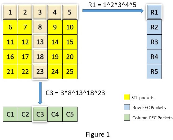
ST-2022-1 works on the concept of generating redundant FEC packets using the STL packets and interleaving transmission of these along with the original STL packets to the destination. These FEC packets are generated by arranging the STL packets in a matrix grid and XOR’ing the contents row-wise and/or column-wise. Users have a choice in selecting the matrix type as below,
- Only Row FEC stream is generated
- Only Column FEC stream is generated
- Both Row and Column FEC streams are generated
In this blog, we will only discuss the third type going forward and dear readers can extrapolate how the first two types would work. For most of the examples discussed below, we will use a 5×5 matrix size.
Generating the FEC packets is done in steps listed below (in no particular order),
- Create Row FEC, Column FEC packets
- Mark the FEC type appropriately based on stream type
- Define the FEC header based on chosen matrix size and STL packets in the matrix
- Offset the destination port number by 2 for the first Stream of FEC packets and 4 for the second Stream of FEC packets
Figure-1 shows how the ST 2022-1 FEC Encoder running on the transmitter side generates the payload part of the Row and Column FEC packets. During my work on developing the stack for STL receivers, packet recovery was only for the STL payload and not its headers. The RTP/UDP/IP header has to be reconstructed by using available data for further processing.
The next part is the definition of the FEC header on the generated packets. All three packet types, STL, Row, and Column FEC have their own sequence numbers in their RTP header. This number is especially important in the FEC header definition as the receiver needs some reference in identifying which Row/Column FEC belongs to which set of STL packets. The matrix size is also important and added in the header.
The below Figure-2 shows the example definitions of Row and Column headers.

Once the FEC packets are generated from the STL Matrix, they are interleaved with the STL Row and Column packets and transmitted. Please note that Figure-3 shows only one example of interleaving, as implemented by an Encoder, and the standard allows for various ordering/interleaving.

The standard also talks about non-block aligned FEC arrangement where the Row and Column FEC stream is not directly XOR’ed as shown in Figure-1 but STL packets in the matrix are picked from every consecutive row to create one Row FEC and so on. This blog will talk about block-aligned FEC only.
SMPTE FEC Decoder
FEC Decoder running on the Receiver side first needs to detect that the received IP stream has added an FEC for packet recovery. A basic check of the packet type on the RTP header should be sufficient to detect this and once the receiver knows about the state, it can start buffering and processing the STL and the FEC packets.
For the Receiver, there are two tasks, to begin with:
- First, differentiate the received packets as STL packets or FEC Row & Column packets
- Second, store them properly to recreate the original matrix as seen previously in example Figure-1. Basically, this operation is to detect the starting point of the STL matrix along with the start of corresponding Row and Column arrays. This operation may need to be done only once if the start of the matrix is detected properly. Once done, the RTP sequence number on each stream will automatically serve as a reference to build subsequent matrices
Check the example diagram in Figure-4 that shows how the matrix start is detected and matrix building starts. Example incoming input packets are shown in the table and we see three matrices being filled based on the information extracted from each packet. From the second matrix, we can clearly see that when the FEC SnBase of the Row and Column stream matches with the RTP sequence number of the STL stream, then the matrix can be built. This operation needs to be done only once and the RTP sequence numbers can be used for building subsequent matrices.

Now coming to the crux of the topic, how does buffering all these help with recovering packet loss?
Let’s look at a few examples that show various packet loss scenarios and you will quickly see how the lost packets are recovered. All the below examples assume that the start of the Matrix has been found after which the RTP Sequence numbers on both STL and FEC streams are sufficient to build subsequent matrices to detect packet loss.
All listed figures from Figure-5 to Figure-10 are scenarios where lost STL packets can be recovered. Please note, that packet loss in only STL streams is required to be recovered and Figure-10 shows an example where FEC packets are lost and such packets need not be recovered.


Some quick points to note,
- Figure-5 is the most common scenario of random packet loss
- From Figure-7, we see that both Column and Row FECs need to be used to recover the three lost packets
- There are some cases where Row Recovery may be possible only after a Column Recovery completes and vice-versa as shown in Figure-7 and Figure-8. The recovery algorithm should be flexible to cover such cases
- From Figure-8, we see that Burst packet loss can also be recovered and Figure-12 shows an example where the recovery tolerance breaks under long burst loss
- Packet loss can be expected on all three streams, Row, Column, and STL. In a given matrix, if FEC packets are lost with all STL packets intact, then no recovery mechanism needs to be executed. This is shown in Figure-10
- From Figure-11, we see an extreme case where one packet loss on STL cannot be recovered because both the corresponding Row and Column FEC packets are also lost
- Any combination of Column recovery and Row recovery can be applied and shown figures are just one example of how packets can be recovered
Design considerations
While FEC helps with the recovery of packet loss, the inherent need to store the packets in a matrix to detect packet loss introduces a jitter on the Fronthaul where the STL packets need to be submitted for further processing.
Consider a scenario where FEC is disabled and one STL packet is received once every 1 ms. Now, with FEC enabled using a 5×5 matrix size, 25 STL packets get stored in the matrix, and only after the packet loss algorithm detects that no packet loss has occurred, all these 25 STL packets are given to Fronthaul in a single burst, once every 25 ms. Consider Figure-9, where 5 lost packets are to be recovered. Note that the algorithm to run the recovery logic also takes up some time. Typically, having an elastic buffer in between the FEC Module and the Fronthaul can help cushion such jitters. Designers can define the elastic buffer based on the configured matrix size. While such an elastic buffer introduces latency in the processing pipeline, this latency seems unavoidable given the nature of how the packet recovery works.
One should also make a note of the extra bandwidth that is occupied by the FEC Streams. If we use Symmetric Matrix sizes, ie, 4×4, 5×5, etc, the chart in Figure-13 shows how the bandwidth needed to carry the redundant FEC packets varies with the matrix size.

We can also define non-symmetric matrices, ie, 5×4, 10×2, 5×8, etc, but I have personally not used or seen this getting used. Although the implementation can be kept generic to support both symmetric and non-symmetric matrices, designers should keep this in mind as well.
Conclusion
In this blog, we see how the SMPTE Standard helps in recovering lost packets at the Receiver end using Row Recovery and/or Column Recovery mechanisms. Users should appropriately choose FEC stream size based on their use case, network conditions, and bandwidth availability. We went through some packet recovery examples under random and burst loss conditions that show the operations and limitations of the standard. The design notes, when incorporating ST-2022-1, are especially important when Jitter and Latency issues are to be mitigated. Some topics like non-symmetric matrices, non-block aligned FEC, single-stream on FEC, Out of order reception of STL packets, etc, were not discussed. The ATSC 3.0 Standard, as defined in A324:2018 [2], uses this SMPTE Standard for robust delivery of STL packets generated from the Scheduler to the Transmitter. This feature is implemented in the Broadcast Radio Head (BRH) [4] product that we have developed for one of our customers.
I hope this information helps in your current or upcoming projects.
Cheers!
References
[1] ST 2022-1:2007 – SMPTE Standard
https://ieeexplore.ieee.org/document/7291470
[2] ATSC 3.0 Standard: Scheduler/Studio to Transmitter Link
https://www.atsc.org/wp-content/uploads/2018/01/A324-2018-Scheduler-STL.pdf
[3] ATSC 3.0 Standard: Physical Layer Protocol
https://www.atsc.org/wp-content/uploads/2016/10/A322-2017a-Physical-Layer-Protocol-1.pdf
[4] Broadcast Radio Head
Broadcast Radio Head